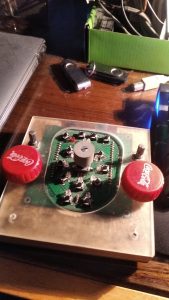
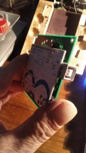
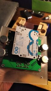
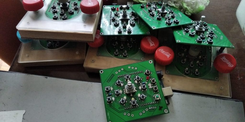
Cirkulino 4 is a midi sequencer based on Arduino UNO R3 development board. It is an advancement from previous ones – and is final. The pcb’s were ordered to be made to professional standards.
A double boot option for arduino was found – to launch it as a native midi device -> https://diyelectromusic.com/2022/03/22/arduino-and-usb-midi/
mocoLUFA MIDI firmware for Arduino Uno -> http://morecatlab.akiba.coocan.jp/lab/index.php/aruino/midi-firmware-for-arduino-uno-moco/?lang=en
This is dual mode firmware for Arduino Uno with 16u2 Midi Serial interface chip. There are two modes in this firmware: USB-MIDI(MocoLUFA) and Arduino-Serial.
INSTRUCTIONS:
– Burn 16u2 on Arduino Uno (check original document) – Windows -> Atmel Flip
– USB-MIDI formware works as default
– To enable Arduino-Serial, add jumper to PIN 4(MOSI PB2) and PIN6 (grand) on ICSP connector of 16U2
– Reset is required to switch the firmware mode
DESCRIPTION:
NEW CIRKULINO SERIES: version 4 – chinese board
– smd 4051 on 8 pins used as IO switches -> switch=input / led=output
– only for 5V 16Mhz atmega 328 based boards: ARDUINO UNO R3
– 8 LEDs / 3 segments – segments of 8 steps programmable via switches
– default step programming is for both segments on midi channel 1 – the basic usage layer -> 8 steps
– variations of this via two top buttons for two midi channels and via two bottom buttons for three segments (1st segment: left button, 2nd segment: right button; 3rd segment: both buttons
– stop/ reset button: brief push = reset sequence
– stop/ reset button for pause=stop: longer push; also selective stop for a single midi channel: a combined push of one of the two midi channel buttons + stop/ reset button
– mode button for forward, backward and palindrome (forth and back)- ping pong
– selective emptying of the single segment: selected segment switch + mode button
ROTARY ENCODER:
– rotary encoder with switch
– basic function: clock speed change
– to set some options use rotary switch to enter this state
– basic mode: sequencer mode: eight led switches select eight basic steps – over three segments
– melodic mode: eight led switches select eight notes to be used
– tonality select mode: eight led switches to select one of eight tonalities
IO pins:
– 10K-22K resistor in series with switches limits the load on pin when in output mode
– normally as output to drive LED
– additional Si diode in series with LED adds 0.7V to about 3V threshold LED – to have high level for reading (high for arduino UNO at 5V is around 3V)
– reading the switches is done in each loop very briefly:
+ switch to input, pull up internal resistor, read the state
+ turn off the internal pull up, switch pin back to output
MULTIPLEXER:
– analog multiplexer HCF4051 to read 8 switches and send to the LEDs the individual pwm values
– multiplexer combines readings (digitalRead()) and writings (analogWrite()) on digital pin (LED_PWM)
– multiplexer switched channel on-resistance is around 60 to 125 ohms – LED limiting resistor not needed
– read switches through multiplexer: internal pullup resistor on pin LED_PWM (20Kohms) pulls input to high
– resistor 10-22Kohms from switch to ground is current limiter when switch pushed and pin is set to write
– white, blue or pink LEDs because of the 3.4 to 3.6V threshold – high luminiscence LEDs needed because of high speed scanning
– additional Si diode on common cathode of all circle LEDs going to the ground – to work on laptops (lower USB 5V psu?)
– potentiometers: analogRead makes problems if slider on top – voltage equals Vcc!? Does not return values! Put a diode or 1K ohms resistor there
– or use only two terminals of 100K to 1Mohms potentiometers -> define internal pullup 20K resistors on analog inputs
OUTPUTS:
– USB-MIDI with mocoLUFA (MIDI firmware for Arduino Uno 16u2 chip – set baudrate to 31250 Hz ) is main data output
OTHER
– with two pots at the bottom set transposition of notes on two channels
– with two pots above set progressive variations of:
– notes and predefined scales
– steps and predefined rhythmic patterns?
Concept view at Ljubljana Mini Maker Faire 2017: Cirkulino_print
The previous versions…
… will continue


